Copyright © 2020-2021 Shenzhen CDTech Electronics LTD. All rights reserved. Site Map Powered by iwonder.cn

display / touch / bonding solutions
display / touch / bonding solutions
An obsolete panel rarely disappears alone. Its datasheet stops being published, its flex leaves production, and the init code that made it work sits in a repository nobody owns. The search for a drop in lcd replacement usually starts with a photograph and a part number that returns nothing.
Nine attributes decide whether an LCD module behaves as a genuine equivalent, and they fail in a predictable order. This guide sets out that order, what each attribute constrains, and a verification sequence that keeps sample orders small.
The nine axes are not equally likely to break a substitution, and they are not equally cheap to repair. A mechanical clash shows up on a bench in minutes, while a firmware mismatch can stay hidden until the first field return.
The order below is empirical. It reflects where substitutions stall when the enclosure cannot change.
A candidate that clears the first four can be sampled with some confidence, since a drawing and a datasheet settle those axes. The last five hold the remaining risk.
Bezel outline first, then bosses, then active area.
The outline is fixed by a tooled front cover, so a millimetre of extra flange or a boss off datum costs a new mould, not a drawing.
The first comparison is not the visible image area. Measure the outside of the bezel, the position of every boss against a common datum, the depth of the threaded inserts and the direction the flex leaves the glass. A candidate two millimetres wider will not drop into a recessed cover, and a boss moved by half a millimetre will not take the screws.
Active area is the second check, since a small offset can be absorbed by the overlay window where the tolerance stack allows it. Draw both outlines at 1:1 over one datum and look for interference rather than difference. The mechanical design guide describes that build-up; keeping the enclosure untouched is covered in finding a drop-in replacement without changing your mechanical design.
Pin numbering is where confident substitutions die. Two tails can carry the same pin count at the same pitch and still be numbered from opposite ends, and a mirrored pinout will power a panel long enough to look promising before it damages the driver. Pin one is marked, but conventions differ between makers, so the drawing of the part in hand is the only safe source.
Classify the pins rather than counting them: power, ground, data lanes, clock, backlight anode and cathode, touch rails, shield. Then buzz the old assembly against its own datasheet, power off. Where the module has a board connector, check the mating part number and insertion depth, because a similar connector from another series will mate and still misalign its contacts. The guide to interfaces and controllers covers the common families.
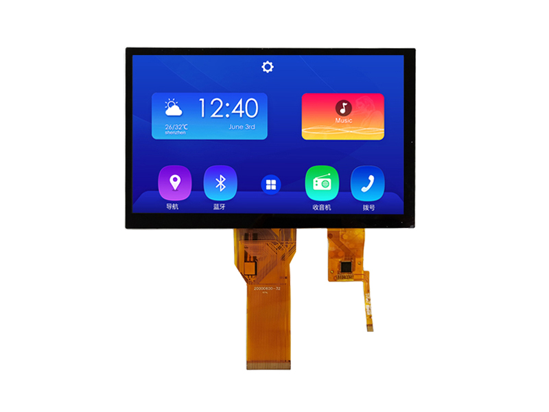
Because both sheets quote the same refresh rate.
Refresh rate and resolution are the two numbers a comparison table shows, and everything that decides whether an image locks sits outside those two columns.
The numbers that matter sit in the timing diagram, not the feature table. Horizontal and vertical porch values, sync width, clock polarity, data enable versus sync mode and pixel clock tolerance must all be satisfied at once, and a controller on a fixed internal timing generator cannot be retuned for a different porch set. That is why a candidate with identical resolution and refresh rate can still tear, shift or fail to lock.
An FPGA or application processor host has room to move, because the timing registers belong to your team; a fixed bridge chip does not. Establish which side of that line the design sits on before sampling, and read the link specification when the interface is serial: lane count and lane rate change the timing budget as much as a parallel bus does. The MIPI DSI specification is the reference there.
Backlight differences are easy to measure and easy to ignore, because a wrong module still lights up. Count the LED strings and the LEDs in each string. A white LED drops roughly 2.8 to 3.4 volts depending on chemistry and current, so six in series need a driver with about 19 volts of compliance while three strings of two need far less voltage and considerably more current.
Drive current matters as much. Constant-current drivers set brightness by current, so a substitute rated at 20 mA per string on a board built for 60 mA will be dim, and the reverse overdrives the LEDs. Dimming method is the third item: PWM on an enable pin, an analogue dim voltage and a serial command are not interchangeable. Match the connector too, since its pin order shows whether the driver sits on the module tail or on your board.
It moves the viewing cone and can invert the image.
A transmissive panel is built around its polariser angles, so a rotated substitute lights up and looks correct head-on while the picture greys out at an angle.
Two panels of the same size and resolution can use opposite polariser orientations. On a twisted nematic cell the off-axis behaviour differs between the top and bottom of the screen, so a module rotated by 90 degrees shows a washed-out or inverted image in the direction the operator stands. In-plane switching cells are more forgiving, but a twisted nematic substitute in an IPS design still shifts colour across a wide panel.
Brightness is the second variable. Crossed polarisers pass only a fraction of the backlight, and a substitute with a thinner diffuser or a different enhancement film can be ten percent dimmer or brighter at the same current. Compare luminance, contrast at the specified angles and the white point, measured the way display measurement standards such as those published by VESA describe, rather than by eye.
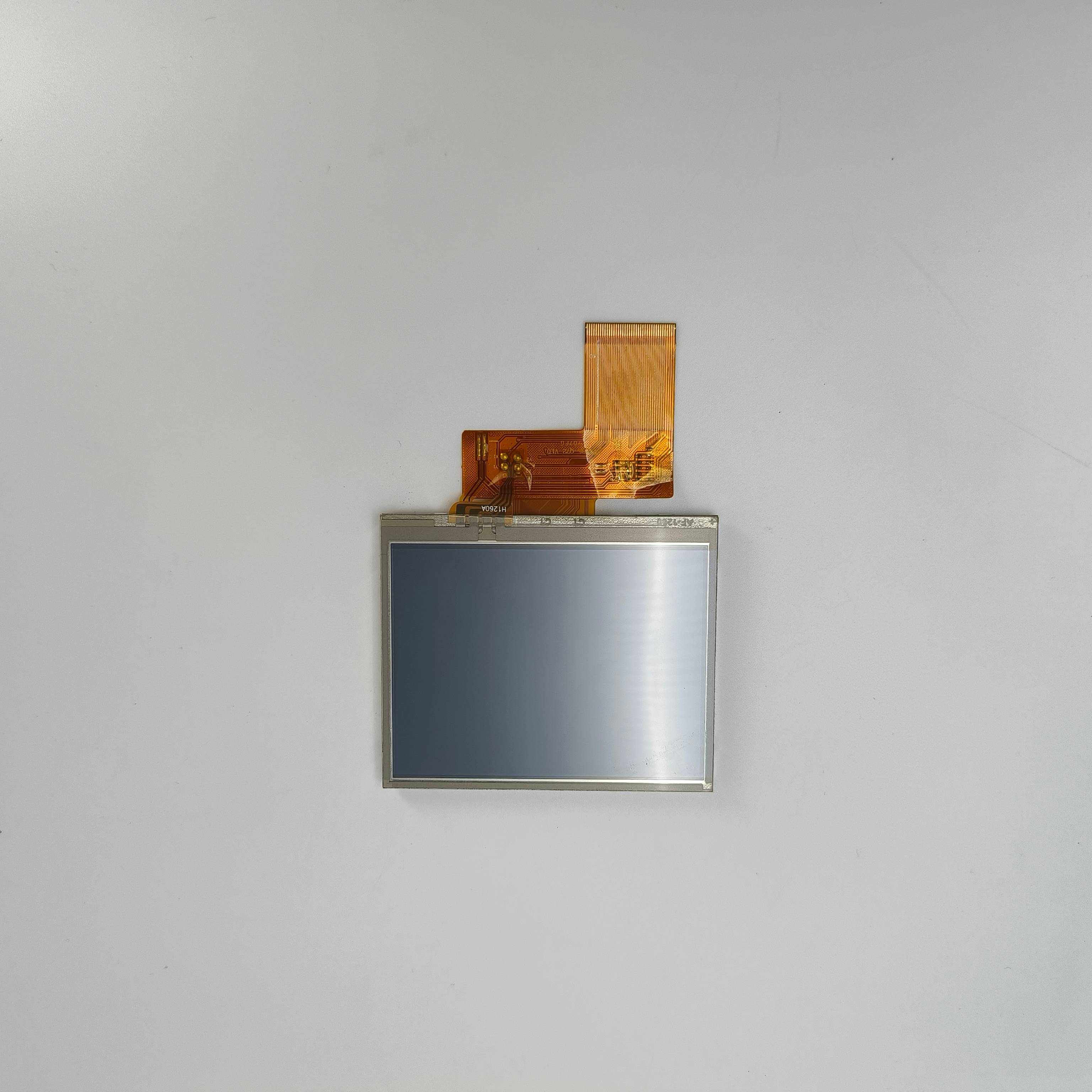
A touch module adds a stack above the display, and that stack is where most near-miss substitutions end. Layer order, cover lens thickness and material, the presence of an optical bond and the sensor pattern all change what the controller sees. An air gap that was acceptable on the original can leave a substitute with reduced edge sensitivity or a visible haze under bright light.
Controller pairing is the second half. The sensor is passive; the controller holds the firmware, tuning and report protocol. A substitute built around another controller family may use the same bus address and still report different coordinates or a different touch count. Confirm the interface, address, interrupt polarity and reset timing, and ask whether the firmware is fixed or configurable.
Bonding quality matters too: bubbles and delamination surface after thermal cycling, and acceptance criteria are normally written against IPC-A-610.
When the thinner stack removes the heat-spreading path.
Thickness alone rarely matters; the aluminium frame, gap pad and air channel that carried heat out of the backlight are what a slimmer module deletes.
Backlight heat has to go somewhere. In a metal-framed module the frame spreads it across the panel and into the chassis. A thinner plastic-framed substitute concentrates the same wattage in a smaller volume, so the LED junction temperature climbs even though the outside feels cooler at the centre, and the brightness and lifetime figures stop describing the part in your housing.
The check is a first-article thermal run at the top of the product ambient range, enclosure closed, display at maximum brightness for an hour. Thermocouples on the frame and an infrared camera give a usable picture in an afternoon. Where the target is automotive or outdoor, the temperature grade behind AEC-Q100 sets the ambient the parts must survive.
Interface voltage is the gate that damages hardware. A 1.8 V I/O panel fed from a 3.3 V bus may work briefly and then fail, and a 3.3 V panel on a 1.8 V bus usually does nothing. Match the I/O rail, check whether the module carries its own regulator, and confirm the power sequence, because many controllers expect the I/O supply before the analogue supply, or a reset pulse of a stated length.
Firmware is the last gate and the least visible. Initialisation code is written for a controller family, and a module built around a different controller needs another sequence, other gamma tables and sometimes a different VCOM setting. Ask for the init code with the sample, not after design freeze. On interfaces that carry an identity, such as LVDS or HDMI bridges, confirm the EDID and supported mode list.
For ESD on the interface and touch tail, IEC 61000-4-2 is the standard most procurement questions refer to.
Verification is cheapest in the order the failures appear, and the sequence below front-loads the checks that cost only desk time. Each step assumes the previous one passed, so a failure sends the candidate back to the supplier rather than forward to the next test.
Two rules keep the sequence honest: never accept a verbal confirmation where a drawing exists, and never let a sample order grow past one unit until the timing table has been read.
The table scores each axis by late-discovery cost and check time, assuming the enclosure is tooled and a bench is available.
| Axis | Check time | Cost if found late |
|---|---|---|
| Mechanical | Under an hour | New mould or rework |
| Connector pinout | Under an hour | Damaged driver, new PCB |
| Timing | Half a day | Tearing, bridge change |
| Backlight | Half a day | New driver, dim panel |
| Optical | A day | Overlay redesign, rejects |
| Touch | A day | New controller, tuning |
| Thermal | Two days | Heatsink or new frame |
| Interface voltage | Two hours | Scrapped panels |
| Firmware | A week | Slipped release, returns |
Firmware and thermal have the worst ratio: they cost most to find late and take longest to check, so they belong early in the schedule despite sitting late in the failure order. Where a substitute needs a modified tail or backlight, the custom sourcing process sets out how the build is specified.
A replacement programme usually needs one candidate confirmed against a stack the team already knows. CDTech can review a drawing set and a timing table against a specific module and say which of the nine axes are covered and which need a sample. Write to [email protected] or use the contact page.
What is the first thing to compare for a drop-in?
Start with the mechanical drawing rather than the image, because the outline and the mounting bosses are the two features fixed by tooling you may not want to change. Place the old and new outlines over a common datum at 1:1 and look for interference. Only then compare active area, flex exit direction and thickness. An active area offset can sometimes be absorbed by the overlay window, while a bezel that is wider will not fit a recessed cover at any tolerance.
Can a different resolution still be drop-in?
Mechanically it can, and electrically it usually cannot without host changes. A panel with another resolution needs a different pixel clock, different porch values and often another lane configuration, and the image will not map one to one onto the existing framebuffer. If the host is an FPGA or an application processor with programmable timing, a resolution change is a firmware project rather than a hardware one. With a fixed bridge chip, treat it as a redesign.
Does backlight voltage matter?
Yes, and it is one of the cheapest mismatches to catch. The forward voltage of a string is set by how many LEDs sit in series, and the driver has a limited compliance range, so a substitute with six LEDs in series will not run from a driver designed for three. Current matters equally, since brightness is set by current and a mismatch either dims the panel or overdrives it. Check string count, drive current and dimming method together, then pin order.
How do I verify pinout before ordering?
Ask for the flex or connector drawing and compare it with the drawing of the part in hand, pin by pin, with the power off. Count the pins, note the pitch and confirm which end carries pin one, because marking conventions differ between makers. Classify every pin as power, ground, data, clock, backlight or touch, since a shared backlight pin is easily missed. A continuity check on a de-soldered old assembly confirms the drawing and takes about ten minutes.
By continuing to use the site you agree to our privacy policy Terms and Conditions.