Copyright © 2020-2021 Shenzhen CDTech Electronics LTD. All rights reserved. Site Map Powered by iwonder.cn

display / touch / bonding solutions
display / touch / bonding solutions
Most 4.3 inch roadmaps treat 480x272 as a format waiting to be retired. It keeps appearing in new specifications because the cost of change sits outside the glass: controller firmware, flex artwork, overlay dies, test fixtures and enclosure tooling all have to move together.
This guide explains what keeps WVGA in production, where a 480x272 layout runs out of pixels, and which replacement routes leave the design intact. It is written for instrument and appliance designers defending a size decision in a specification review.
A 480x272 module is more than glass and a driver. Around it sits a set of assets a programme inherits the moment it selects the format: an FPC artwork, a bed-of-nails test fixture, a backlight reflector drawing, an overlay die and a firmware timing table already debugged.
That is why the format outlives its pixel count. When a panel ships in volume for instruments and appliance panels, reusing the tooling costs less than redesigning the glass, and a new programme often starts from an existing flex drawing and fixture.
The persistence is economic before it is technical: a team asking why the format remains available is really asking whether its own tooling survives a change. The industrial LCD display range shows how many sizes share that base.
Fixed-timing controller classes still drive it natively.
Parallel RGB timing generators, MIPI DSI bridge parts and low-cost SPI front ends all list the format, so a second source usually arrives without a board respin.
At 480x272 and 60 Hz the pixel clock lands near 9 MHz including blanking, slow enough for a controller with no frame buffer or a small SRAM buffer refreshing a static image. Such parts expose a fixed timing table and stay in production because instrument volumes do not justify a new mask set.
The supply base is wide but shallow: plenty of controllers produce the timing, yet few are interchangeable pin for pin. Porch values, sync polarity and pixel clock range decide whether a replacement drops into an existing build. A DSI bridge links host and panel; the MIPI DSI specification defines that link, and the interfaces and controllers guide covers the board side.
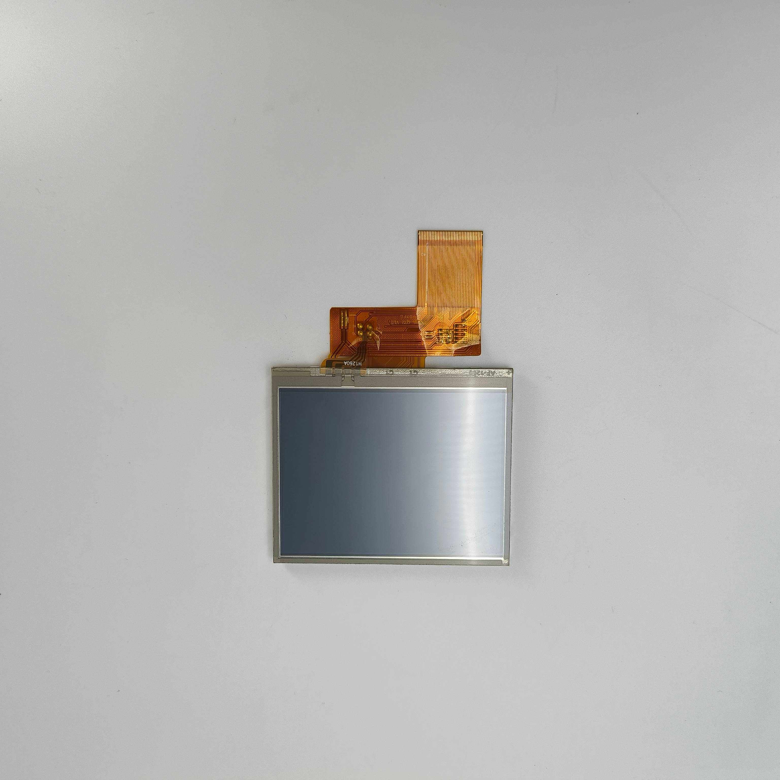
The format provides 130,560 pixels across roughly 95 x 54 mm. That is enough for a control panel built from fixed-function blocks and not enough for a dense application window, so the useful question is which patterns still fit.
| Interface element | Practical minimum | What fits at 480x272 | Where it breaks |
|---|---|---|---|
| Numeric keypad | 56 px key pitch | 8 columns by 4 rows, 32 keys | A fifth row or 20 mm keys |
| Scrolling text list | 14 px type, 46 px row | 5 rows below a header | 12 or more rows with a scrollbar |
| Data table | 52 px per column | 8 columns, no units row | Units and a second decimal |
| Trend chart | 180 px plot height | One axis, three gridlines | Two labelled y-axes |
| Status bar plus soft keys | 40 px top, 48 px bottom | One line each | A two-line alarm banner |
The break point is rarely the resolution alone. It arrives when two patterns compete for the same 272 rows, or when a table needs its unit column and the type drops under 12 px.
RGB888 versus RGB666 is often treated as a colour-depth preference. On a 4.3 inch module it is a routing decision: 24 data lines instead of 18, plus clock and syncs, on a flex that already carries backlight returns and sometimes a touch tail.
Depth separates cleanly. RGB888 gives 16,777,216 colours and RGB666 gives 262,144, with frame rate control dithering between adjacent levels. At 480x272 the difference shows in photographs, dimming ramps and gradients far more than in flat interface colour.
The interface also fixes the controller class. A 24-bit output stage needs a wider internal bus and more pins, which pushes package size and layer count, while an 18-bit part on six fewer conductors can shrink the flex by several millimetres at 0.5 mm pitch. Where the screen shows icons and bar graphs, RGB666 removes conductors without a visible penalty. VESA display standards remain the reference for describing those timing and bit-depth combinations.
Roughly 14 mm more width and 12 mm more height.
The active area grows from about 95 x 54 mm to 109 x 65 mm, and the module outline, bezel and viewing aperture generally grow faster than the glass does.
Those numbers understate the mechanical cost. A module outline adds a border on every edge, a flex exit needs clearance at one side, and a capacitive overlay adds a bonded stack that must sit inside the same bezel opening. An enclosure built around 4.3 inch often has no 14 mm to give.
The bar formats are the intermediate option. A 4.6 inch 800x320 module measures about 108 x 43 mm, wider but 11 mm shorter than WVGA, which suits a panel-mount product where height binds and width comes from the extrusion. A changed window opening also invalidates the gasket path behind an ingress claim, and IEC 60529 is the basis most buyers test against.
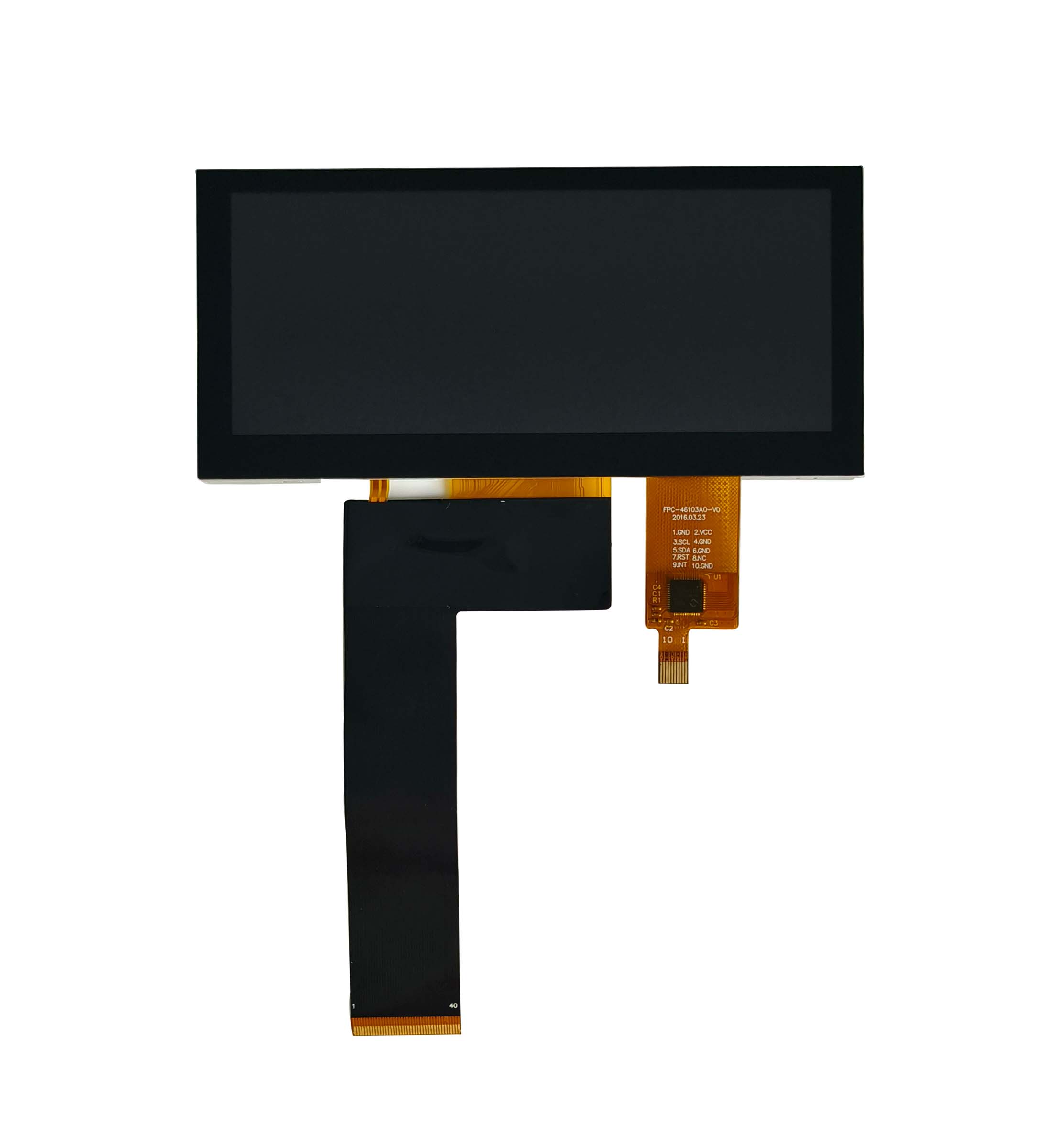
The flex, bosses and timing table stay as they are.
A genuine same-size swap keeps the outline, hole pattern and bus width, so only the panel, its gamma data and possibly the touch overlay change hands.
Same-size means the drawing matches, not that the part number is familiar. Two 4.3 inch 480x272 modules can differ in flex exit direction, tail length, connector pitch and backlight current while sharing identical glass.
Each item that survives removes a re-qualification step. The panel technology guide explains which of these are fixed by the glass and which move with a module maker's assembly choices.
In fixed-function instruments with long production lives.
Lower source count, a single-chip controller, an 18-bit bus and depreciated tooling typically outweigh a newer format's better specification on most long-lived fixed-function instrument programmes.
Cost per display is not the panel price alone. It is panel, driver, backlight, flex, connector, test time and the board area the interface occupies. At 480x272 most of those terms are smaller than at 800x480 in the same diagonal: fewer source outputs, fewer conductors, no LVDS receiver, and a two-layer board where a wider bus might need four.
The backlight follows the pixel geometry. Larger pixels leave a wider aperture ratio, so the same LED power produces more luminance through the same polariser stack, which allows a smaller driver and less heat. Volume economics finish the argument, because a format shipping for two decades carries amortised tooling and multiple qualified sources. Qualification evidence for mature silicon is usually published against JEDEC reliability standards.
Overlay tooling fixes the outline more tightly than the panel drawing does. A module with a printed bezel, an optically clear adhesive layer and a cover glass has an outer dimension set by the die, and its window is cut for one specific active area position. A panel whose active area shifts by a millimetre makes the overlay unusable even when the diagonal matches.
Registration drives the tolerance budget. The print sits on the underside of the cover glass, aligned to the sensor or resistive tail, and the aperture edge has to clear the active area by enough to hide the border without covering pixels.
Touch construction sets the rest. A capacitive sensor carries its own ITO pitch, independent of resolution, so a resolution change does not force a sensor redesign; a four-wire resistive panel instead constrains the tail exit and fold radius. The overlay die is the tool that decides how much of the enclosure can stay.
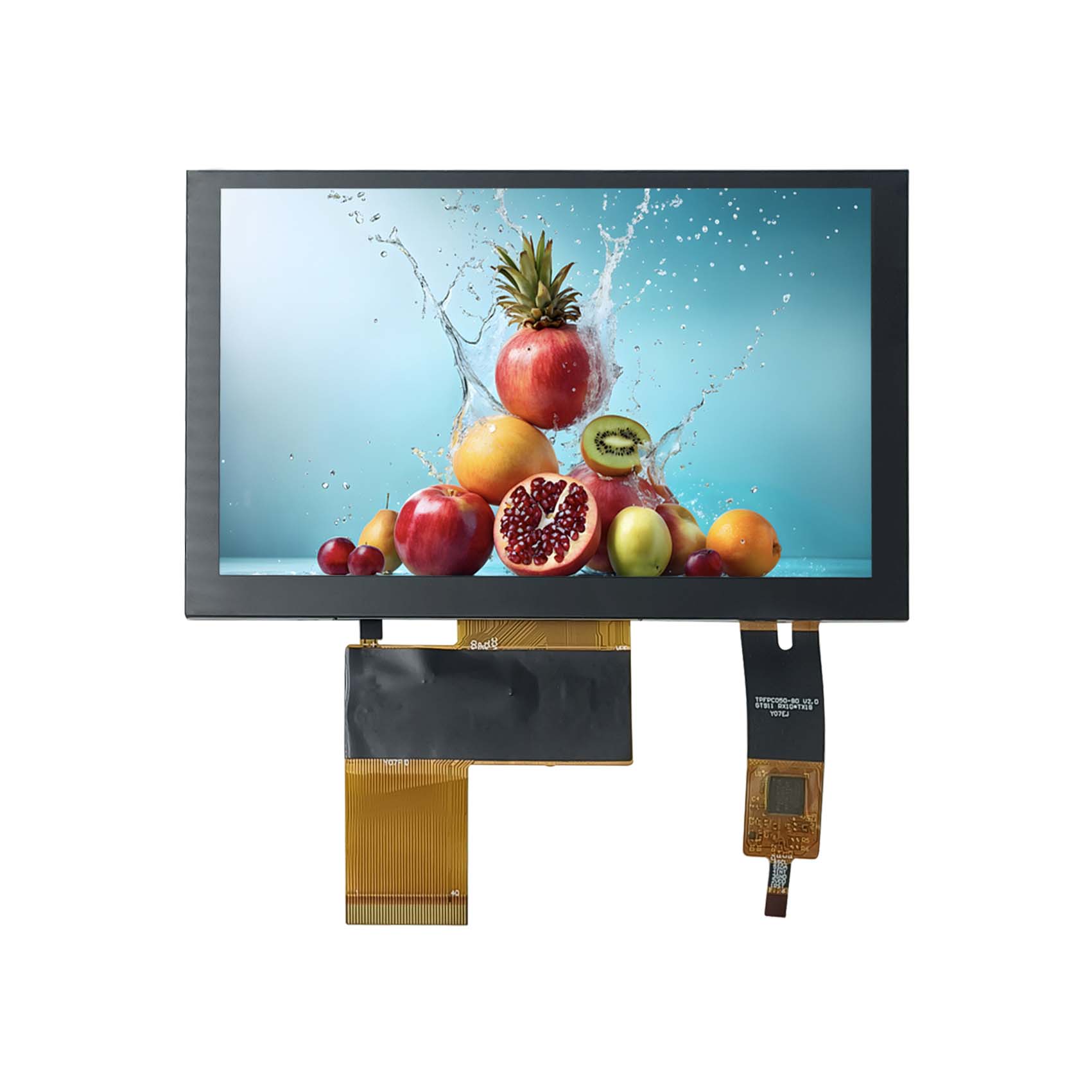
Supply pressure on a mature format rarely arrives as a sudden stop. It shows up as longer allocation windows and fewer second-source options, and the response depends on which layer can move: firmware, flex, enclosure or product definition.
A second source in the same format is cheapest and preserves every asset, provided the drawing matches on tail, connector and backlight current. A 4.3 inch 800x480 module doubles the pixel count in the same diagonal and needs roughly 30 MHz of pixel clock, which usually means RGB888 or a DSI link and a new flex.
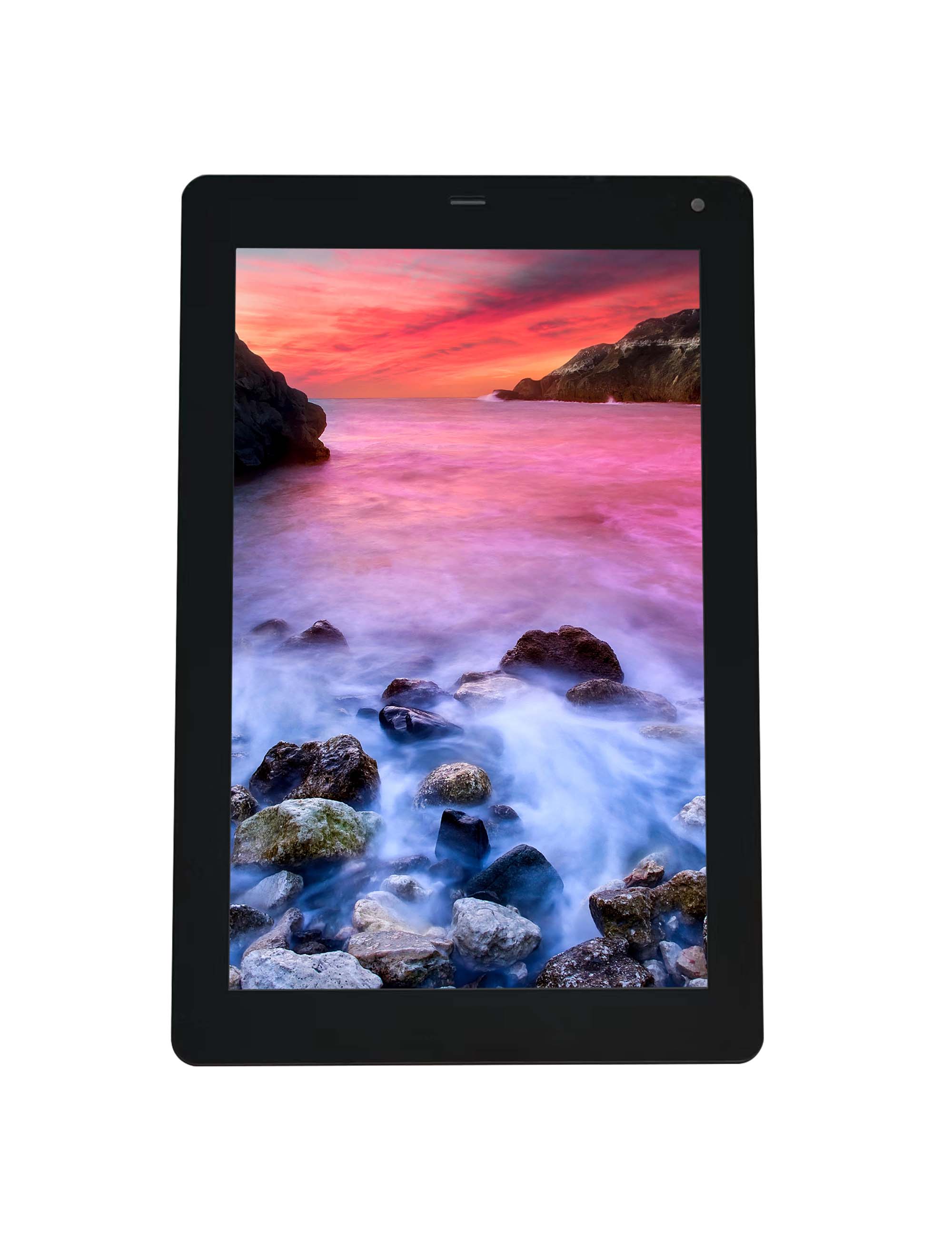
Beyond that the product definition changes: a 10.1 inch 1200x1920 portrait module is a platform decision rather than a substitution. Before committing, check the management system behind a new source: ISO 9001 registration is the baseline a quality team will ask about.
Matching a replacement to an existing enclosure starts with the drawing, not the datasheet headline. CDTech can compare a current 4.3 inch module against the timing, flex and overlay constraints in your build and set out which routes keep the tooling. Write to [email protected] or use the contact page to start that comparison.
Why is 480x272 still common?
The format survives because of the tooling around it rather than the glass itself. Flex artwork, test fixtures, overlay dies and firmware timing tables were paid for by earlier programmes, so a new design inherits them at no cost. That keeps a wide choice of sources in production long after the pixel count stops being impressive. Instrument and appliance volumes are also steady and predictable, which suits a mature panel line and does not reward a mask set change. The result is a format that remains the lowest-risk option for a fixed-function interface.
What is the next size up from 4.3 inch?
The next practical rung is 5.0 inch at 800x480, which adds roughly 14 mm of width and 12 mm of height over a 4.3 inch module. Between the two sits the bar format, a 4.6 inch 800x320 panel of about 108 x 43 mm, wider than WVGA but shorter. A 4.3 inch 800x480 part is the same size on the outside and a different design on the inside, because the pixel clock rises to about 30 MHz and the flex usually has to change.
Does WVGA support 24-bit colour?
Yes, and the distinction is the interface rather than the resolution. A 480x272 panel can be driven at RGB888 with 24 data lines, giving 16.7 million colours, provided the controller and flex carry them. RGB666 is more common at this size because 18 data lines suit a narrower flex, a smaller package and a two-layer board. The visible difference appears in gradients, photographs and dimming ramps rather than flat interface colour, so a control panel made of icons and text rarely justifies the extra conductors.
Which touch overlay suits 4.3 inch?
Both main types fit, and the choice follows the input task rather than the size. A four-wire resistive overlay suits stylus entry, gloved use and passive cost pressure, at the price of a softer image from the air gap and a shorter life at the edges. A capacitive overlay suits finger input, gestures and a flush bonded surface, but needs an ITO sensor, a controller and a bonded stack that raises the module cost. For a fixed keypad layout, resistive is often adequate; for pinch and swipe, capacitive is the only workable option.
By continuing to use the site you agree to our privacy policy Terms and Conditions.